Previous article:
Assemble Power | Data Card to Structure
Next article:
Light On
All operations are carried out under power off.
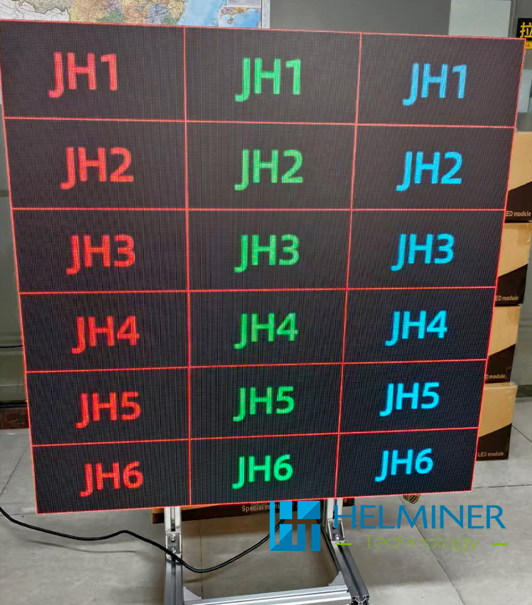
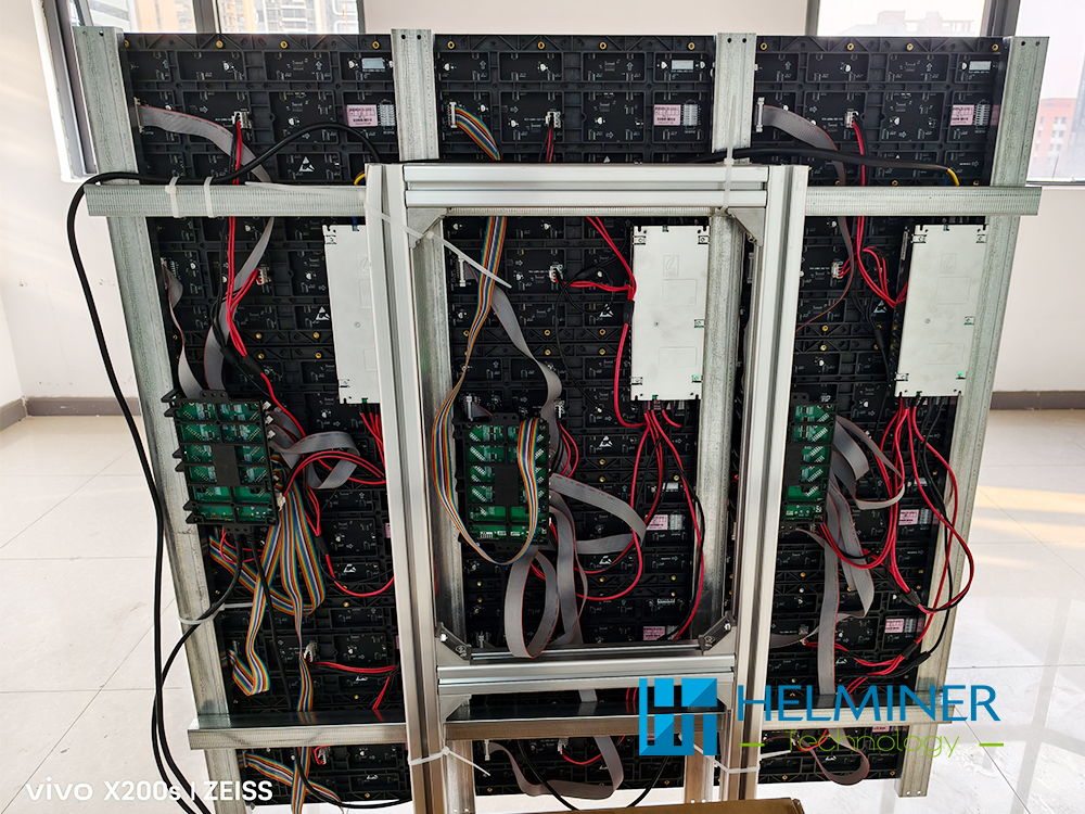
Basic Sample Box : Adopting a 3-column 6-row design | The project used a total of 18 modules (2 of which were spares).
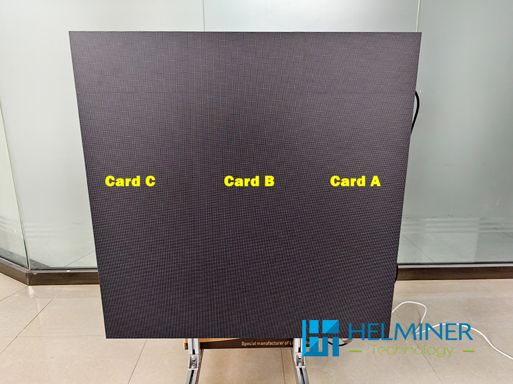
- Data Card DH7512-S : 3pcs
- One Data Card drive 6 pcs LED module
- Data signal transmission direction : TU20 -> Data Card A -> Data Card B -> Data C
- One power supply 6pcs LED module + 1pcs data card
-
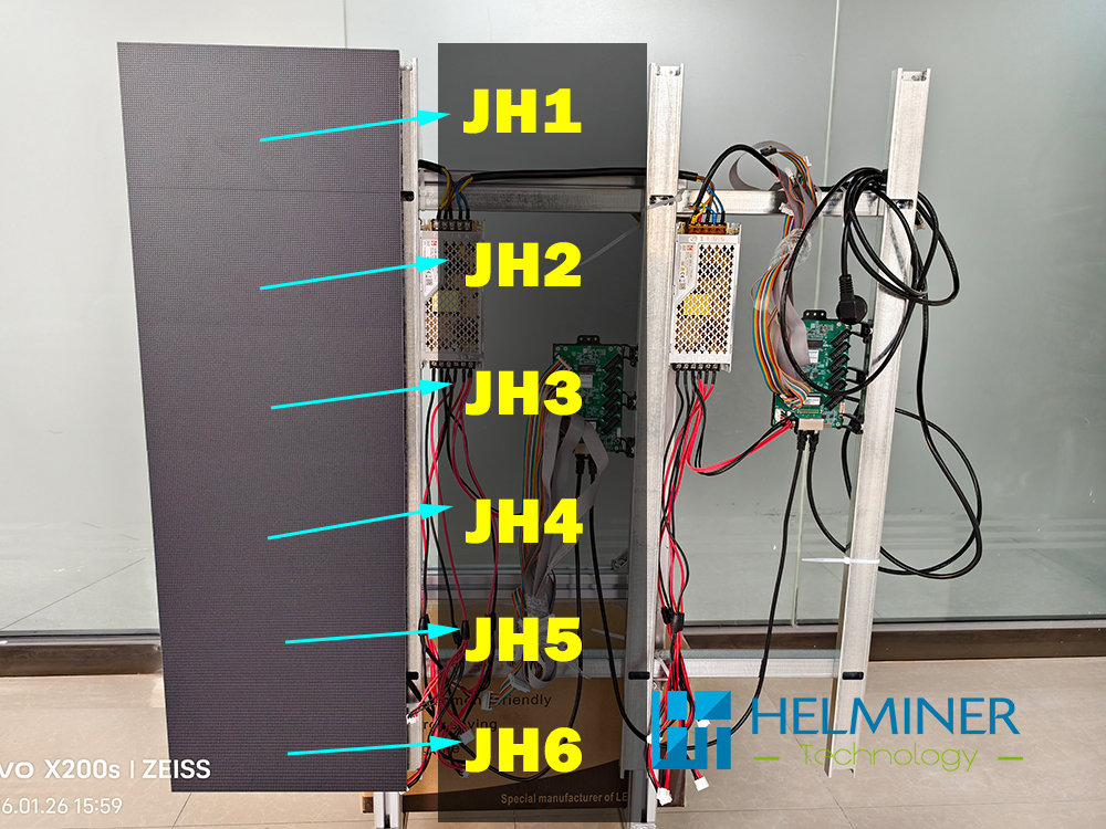
One data card drive 6pcs LED Module
Please install strictly according to the sequence number. Any wrong sequence will cause the display to malfunction.
Assemble Module Detail
Detail :
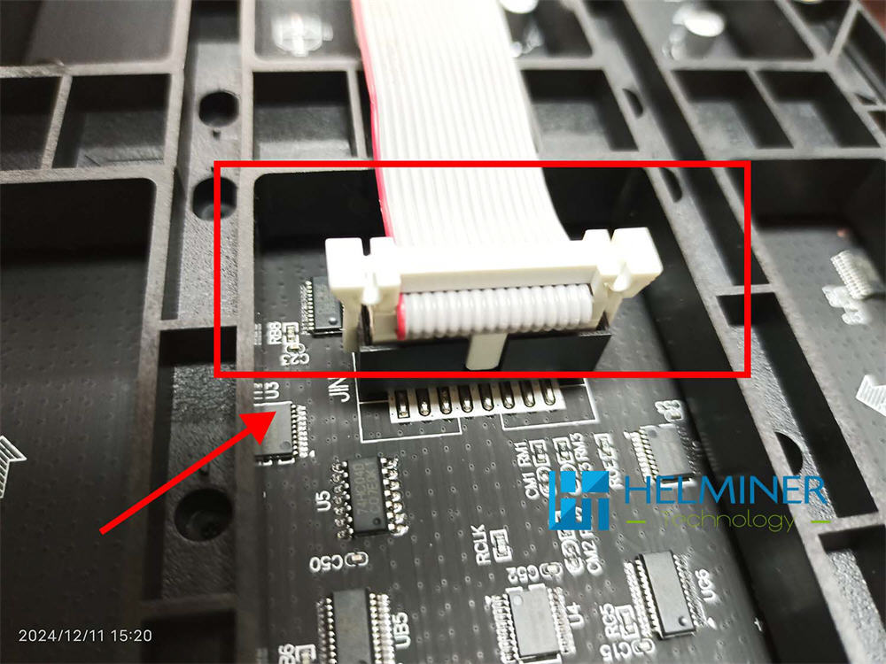
The data cable has a positive and negative insertion direction, which must be consistent with the direction in the picture. There is a square protruding port that is consistent with the concave port.
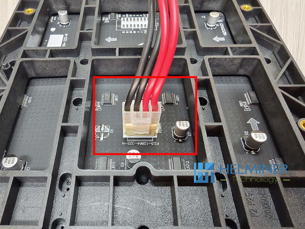
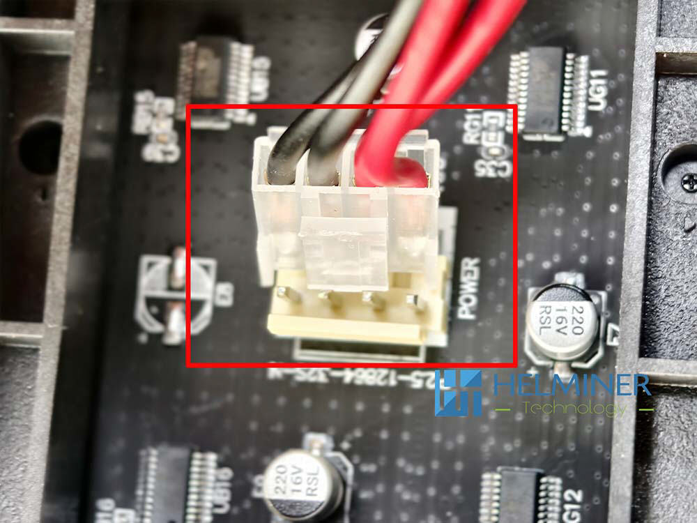
The connection of the power cord is also direction-dependent, please refer to the position of the red frame in the picture.
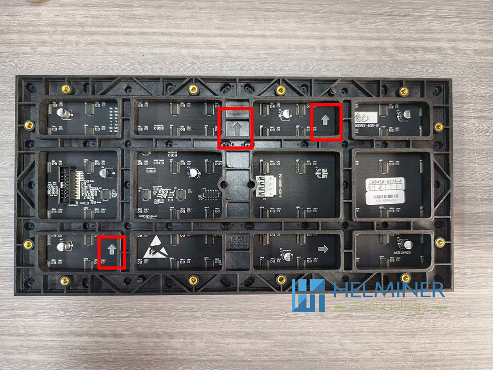
Make sure the arrow is facing upwards when installing.
Basic LED Wall Sample Installation
Previous article:
Assemble Power | Data Card To Structure
Next article:
Light On