Previous article:
Assemble Magnet | Data Card Cable | Power Cable
Next article:
Assemble Module To Structure
Start assembling the LED power
All operations are carried out under power off.
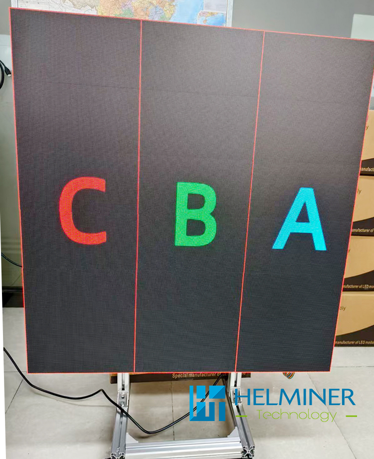
Installation complete display

- The basic LED Wall : uses a total of three data cards, which are strictly distinguished by order, from left to right as C - B - A.
-
Control signal direction :
TU20 -> Data A -> Data B -> Data C
Please read carefully according to the details
-
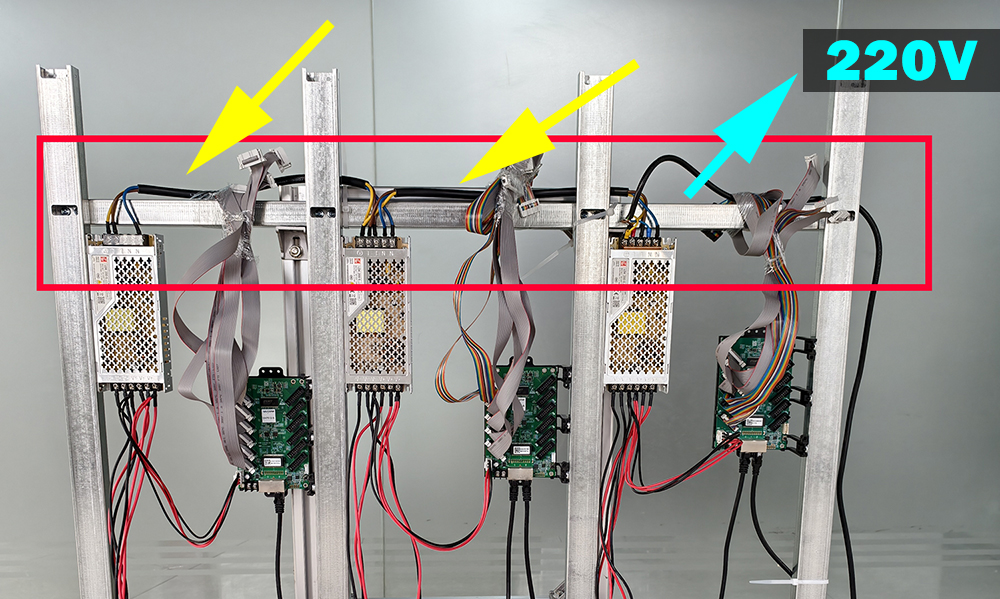
After the LED power and data card are installed,
connect the 220V main power cable to the LED Power .
connect the DC5V data card power cable ,
connect the network cable between the data cards.
(Each data card has two network cable ports, and you can connect them in any order.)
Carefully check that all connections are correct.
Once confirmed, turn on the power and check that the power indicator and data card indicator are on. Turn off the power after the check is complete.
Assemble Detail :
Assemble the power and data card
Basic Sample box
The power supply was secured using screw holes numbered 2-3.
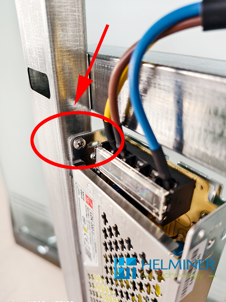
Note :
We recommend using M3.5/M3 self-tapping screws for mounting (customers need to prepare their own).
Connect the power supply using the included power cable
Yellow mark
The main power cord needs to be provided by the customer.
Cyan mark
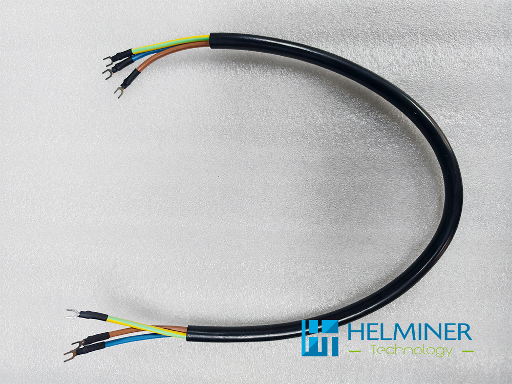
LED power connect cable
Data Card
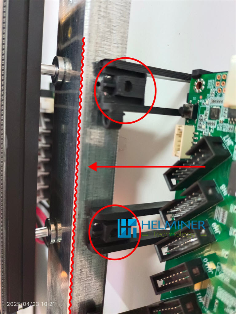
The data card holder has a built-in magnet and can be directly attached to the "A" structure.
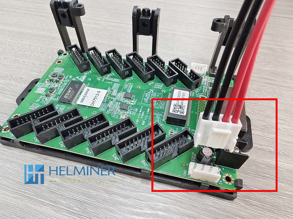
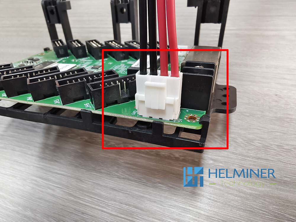
The connection of the data card power cable is also direction-dependent, please refer to the position of the red frame in the picture.
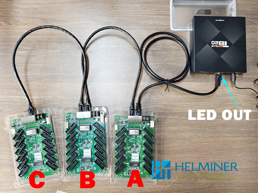
All data cards have pre-installed programs and are numbered. Please connect them to the TB20 controller in the correct order.
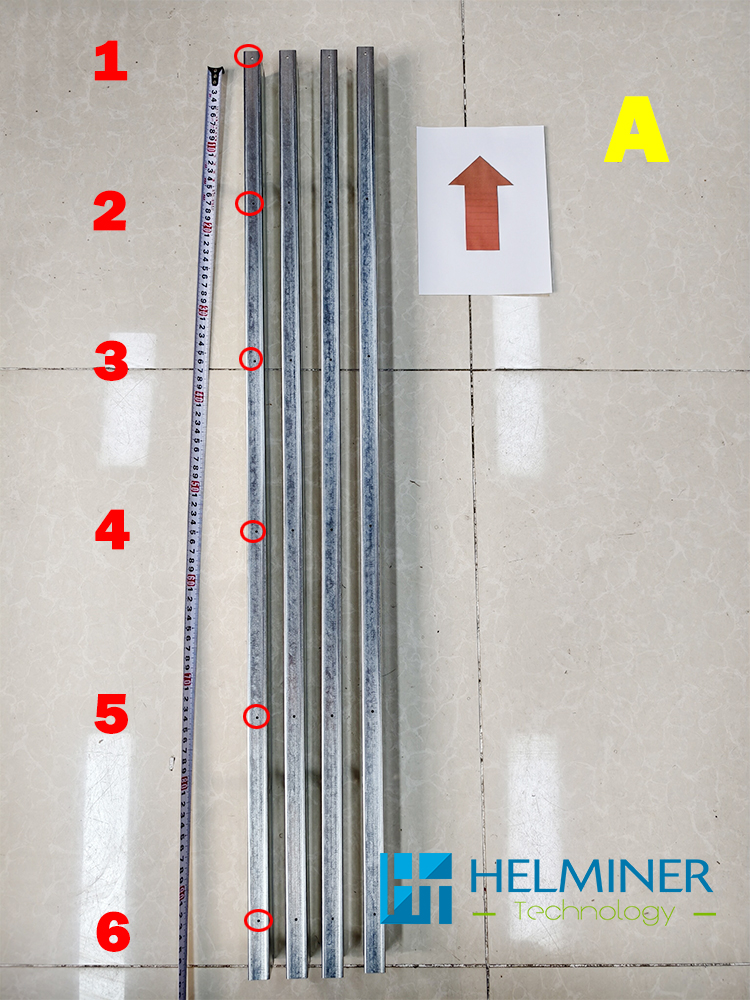
1 Meter network cable is used to connect the data card.
Each data card has two network cable ports, which can be connected to either one.
5 Meter network cable is used to connect the data card (A) and the TB20 controller.
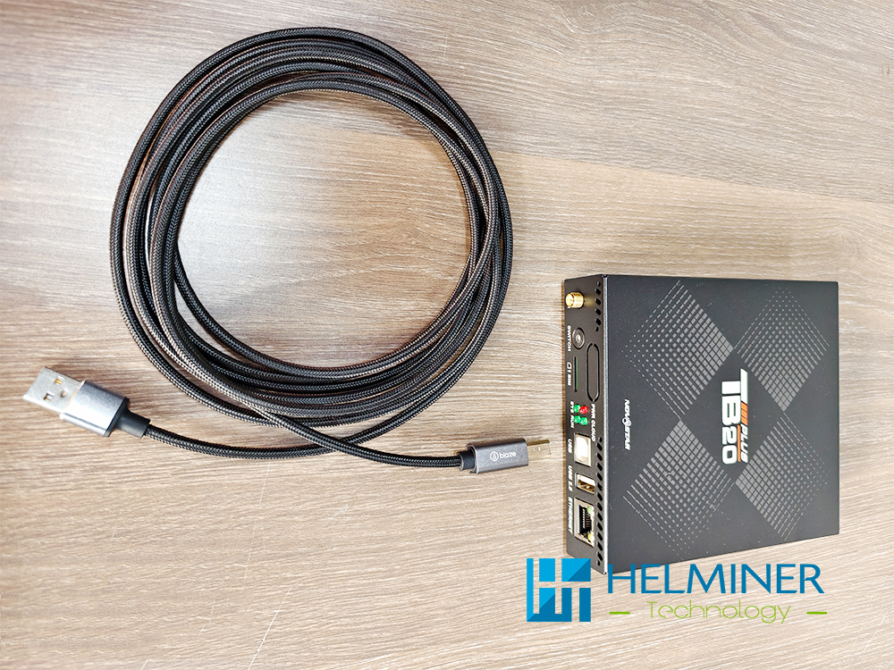
When operating the TB20 controller using a computer, a USB control cable needs to be connected.
Basic LED Wall Sample Installation
Previous article:
Assemble Magnet | Power Cable | Data Card cable
Next article:
Assemble Module to Structure