Note :
For sample box orders placed after June 2025, Please check the 6 Rows * 3 Columns
Following is the 9 Rows x 2 Columns
Please read carefully according to the details
- Complete the LED WALL back support structure according to the drawing
-
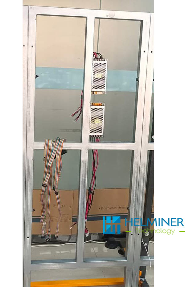
Installing the power and data cards to the structure .
Before securing the power and data card to the structure :
A : First install the 5V LED module power cable and the 5V data card power cable
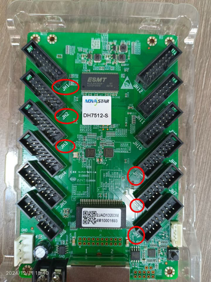
B : Insert the flat data cable into the corresponding interface of the data card in advance (completely corresponding to the drawing) -
After the LED power and data card are installed,
connect the 220V main power cable to the LED Power .
connect the DC5V data card power cable ,
connect the network cable between the data cards.
(Each data card has two network cable ports, and you can connect them in any order.)
Carefully check that all connections are correct.
Once confirmed, turn on the power and check that the power indicator and data card indicator are on. Turn off the power after the check is complete. - Instalaltion GOB LED Module
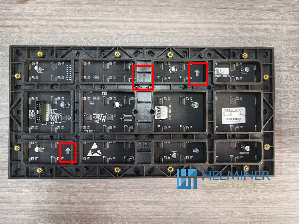
Make sure the arrow is facing upwards when installing.

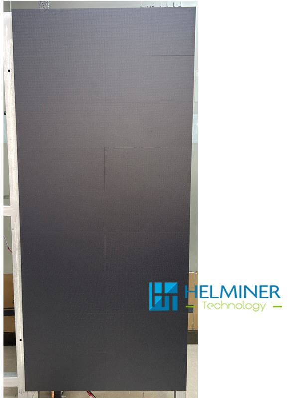
The completed cabinet viewed from the front .
The positions of the data interface and the unit board must be exactly the same as in the picture.

One power supply 6pcs LED module + 1pcs receiver data card
Please distribute the power strictly according to the designed quantity, otherwise it will cause damage to the power supply and the display.
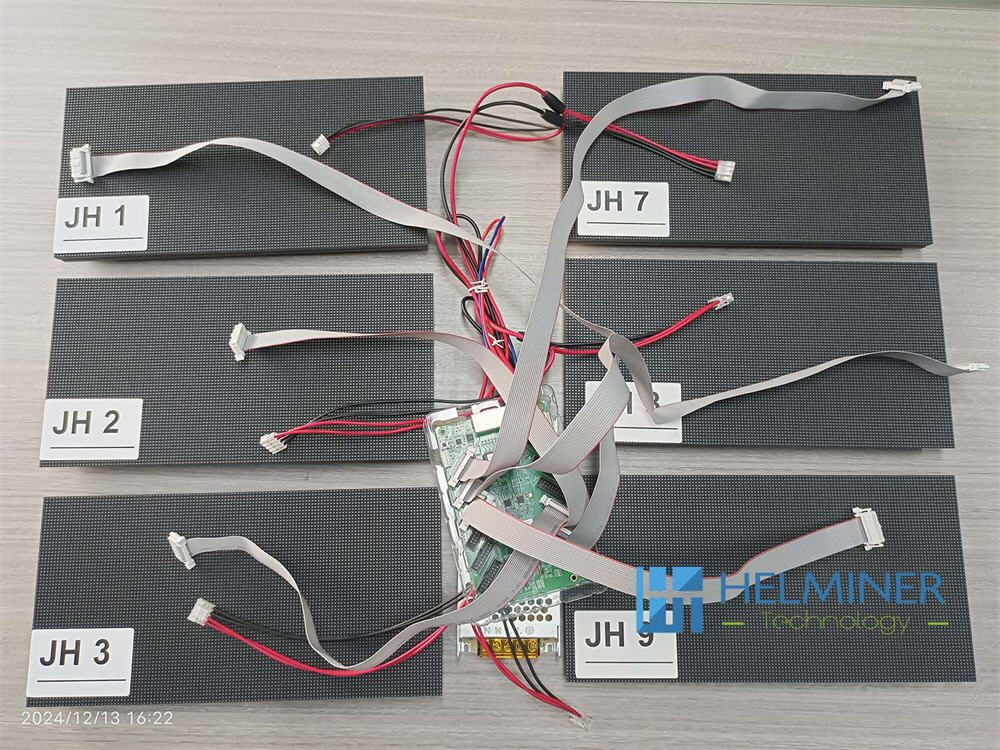
This sample box use the JH1, JH2, JH3, JH7, JH8,JH9 6 DATA-PORT
Please install strictly according to the sequence number. Any wrong sequence will cause the display to malfunction.
Testing :
The data card has a built-in test program.
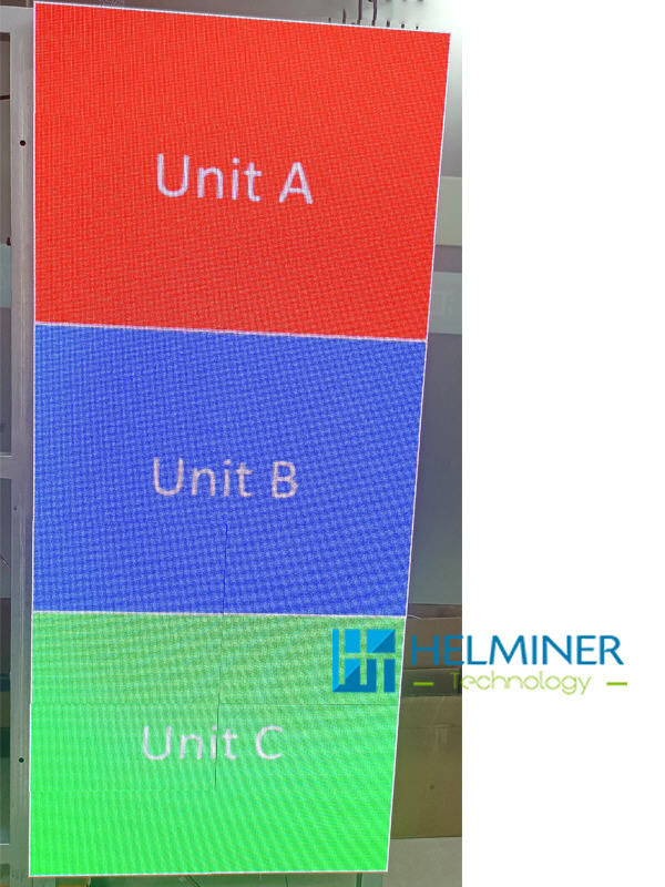
After installing a unit (UNIT A), 3 Rows x 2 Columns
carefully check whether the power cable is inserted correctly,
the data cable is inserted in the correct direction,
and ensure that all connections are in place and there are no loose connections.
Turn on the power,
Press the test button of the datacard, the screen will show as follows
Facebook :
Test Video
After the display is correct, turn off the power.
Continue to install the remaining two units
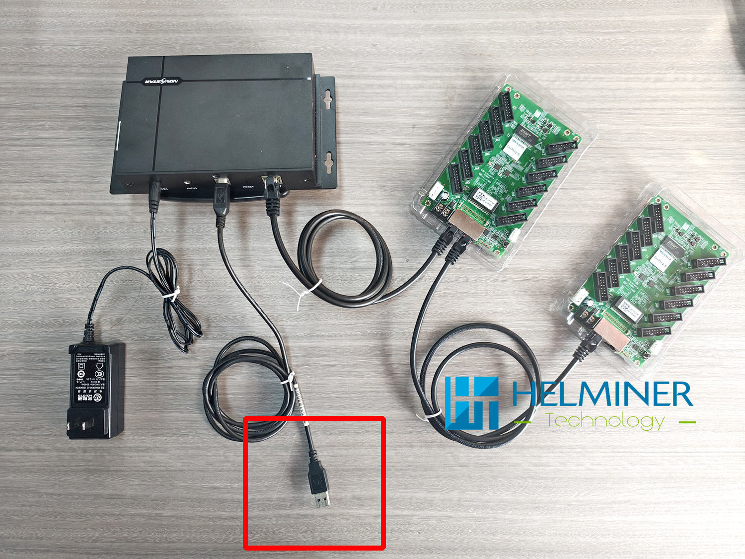
Each datacard has two network ports for cascading,
which can be connected in any order.
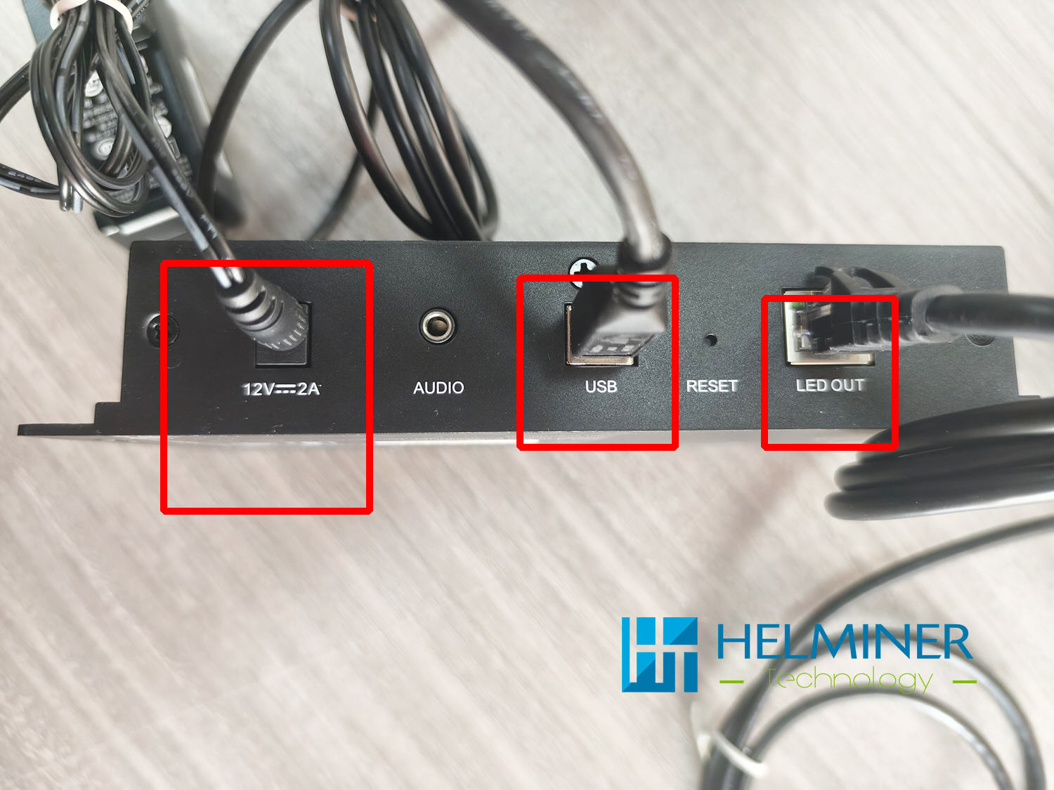
- 12V-2A is the LED Controller Power Interface
- USB Data Interface : Used to connect to a computer
- LED OUT Interface : connect to the datacard
After you complete the physical connections,
please contact our sales manager for more information on installing and debugging the control system software.
Home > LED Wall Blog > Basic Sample Box - Assemble > Light on the basic sample box